Note
Hello, welcome to the SunFounder Raspberry Pi & Arduino & ESP32 Enthusiasts Community on Facebook! Dive deeper into Raspberry Pi, Arduino, and ESP32 with fellow enthusiasts.
Why Join?
Expert Support: Solve post-sale issues and technical challenges with help from our community and team.
Learn & Share: Exchange tips and tutorials to enhance your skills.
Exclusive Previews: Get early access to new product announcements and sneak peeks.
Special Discounts: Enjoy exclusive discounts on our newest products.
Festive Promotions and Giveaways: Take part in giveaways and holiday promotions.
👉 Ready to explore and create with us? Click [here] and join today!
5.1 Microchip - 74HC595
Integrated circuit (integrated circuit) is a kind of miniature electronic device or component, which is represented by the letter “IC” in the circuit.
A certain process is used to interconnect the transistors, resistors, capacitors, inductors and other components and wiring required in a circuit, fabricate on a small or several small semiconductor wafers or dielectric substrates, and then package them in a package , it has become a micro-structure with the required circuit functions; all of the components have been structured as a whole, making electronic components a big step towards micro-miniaturization, low power consumption, intelligence and high reliability.
The inventors of integrated circuits are Jack Kilby (integrated circuits based on germanium (Ge)) and Robert Norton Noyce (integrated circuits based on silicon (Si)).
This kit is equipped with an IC, 74HC595, which can greatly save the use of GPIO pins. Specifically, it can replace 8 pins for digital signal output by writing an 8-bit binary number.
Schematic
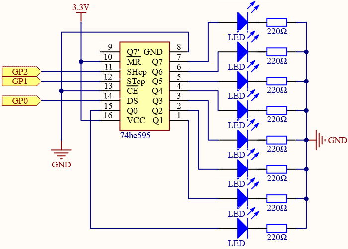
When MR (pin10) is high level and OE (pin13) is low level, data is input in the rising edge of SHcp and goes to the memory register through the rising edge of SHcp.
If the two clocks are connected together, the shift register is always one pulse earlier than the memory register.
There is a serial shift input pin (Ds), a serial output pin (Q) and an asynchronous reset button (low level) in the memory register.
The memory register outputs a Bus with a parallel 8-bit and in three states.
When OE is enabled (low level), the data in memory register is output to the bus(Q0 ~ Q7).
Wiring

Code
Note
Open the
5.1_microchip_74hc595.pyfile under the path ofeuler-kit/micropythonor copy this code into Thonny, then click “Run Current Script” or simply press F5 to run it.Don’t forget to click on the “MicroPython (Raspberry Pi Pico)” interpreter in the bottom right corner.
For detailed tutorials, please refer to Open and Run Code Directly.
import machine
import time

sdi = machine.Pin(0,machine.Pin.OUT)
rclk = machine.Pin(1,machine.Pin.OUT)
srclk = machine.Pin(2,machine.Pin.OUT)

def hc595_shift(dat):
    rclk.low()
    time.sleep_ms(5)
    for bit in range(7, -1, -1):
        srclk.low()
        time.sleep_ms(5)
        value = 1 & (dat >> bit)
        sdi.value(value)
        time.sleep_ms(5)
        srclk.high()
        time.sleep_ms(5)
    time.sleep_ms(5)
    rclk.high()
    time.sleep_ms(5)

num = 0

for i in range(16):
    if i < 8:
        num = (num<<1) + 1
    elif i>=8:
        num = (num & 0b01111111)<<1
    hc595_shift(num)
    print("{:0>8b}".format(num))
    time.sleep_ms(200)
When the program is running, num will be written into the 74HC595 chip as an eight-bit binary number to control the on and off of the 8 LEDs.
We can see the current value of num in the shell.
How it works?
hc595_shift() will make 74HC595 output 8 digital signals. It outputs the last bit of the binary number to Q0, and the output of the first bit to Q7. In other words, writing the binary number “00000001” will make Q0 output high level and Q1~Q7 output low level.